Device Modules
The assembly of the device modules is largely the same for all three modules. Start with the module cloest to the power module and work over to the farthest.
Each module has four screw tie points. These are used to secure wires to make connections between the various components.
The pinout will be explained during assembly, but to summarize.
- Ground in from previos module, Fan Ground
- Ground out to next module, DC plug ground
- Power in from previous module, Power out to next module, power in to switch
- Switched power out from switch, Power to fan, power to DC plug
From the front of the device module, set the DC plug into the hole in the back of the module. Make sure the two wires exit out the back of the module. Secure the plug in place with the plastic nut.
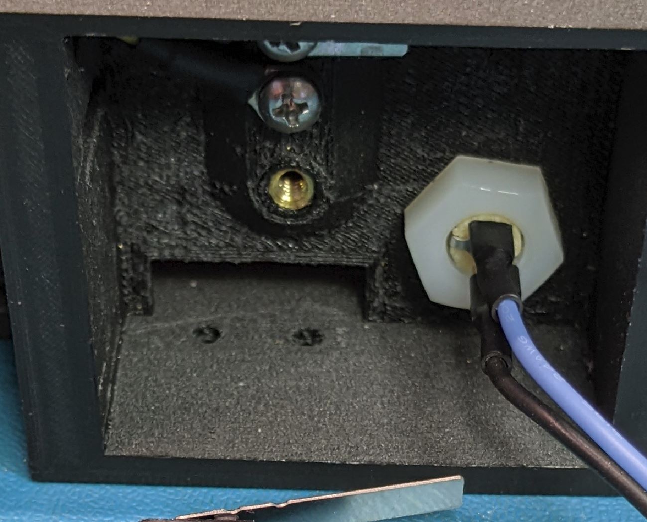
Slide the switch in from the back of the case into the opening in the back wall.
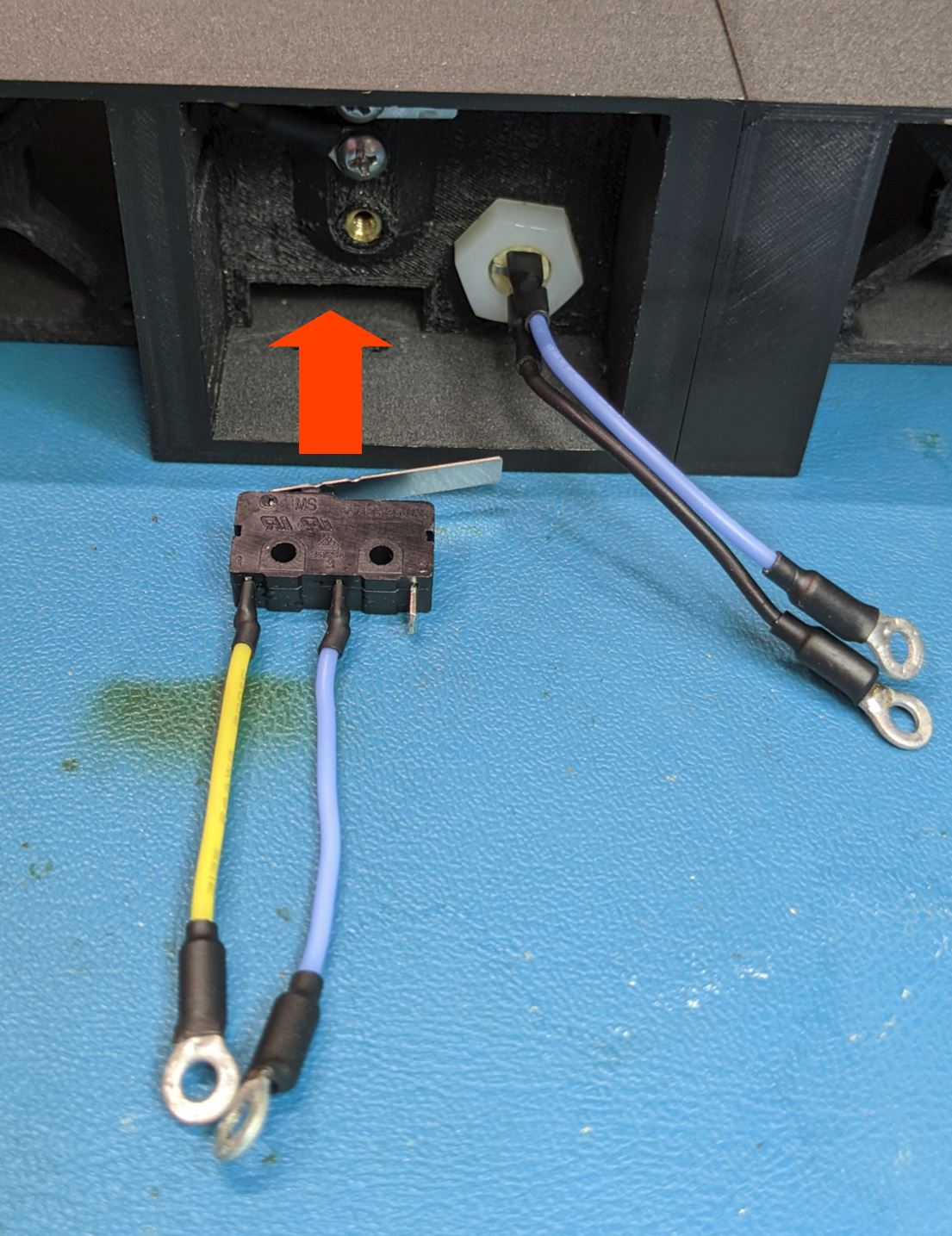
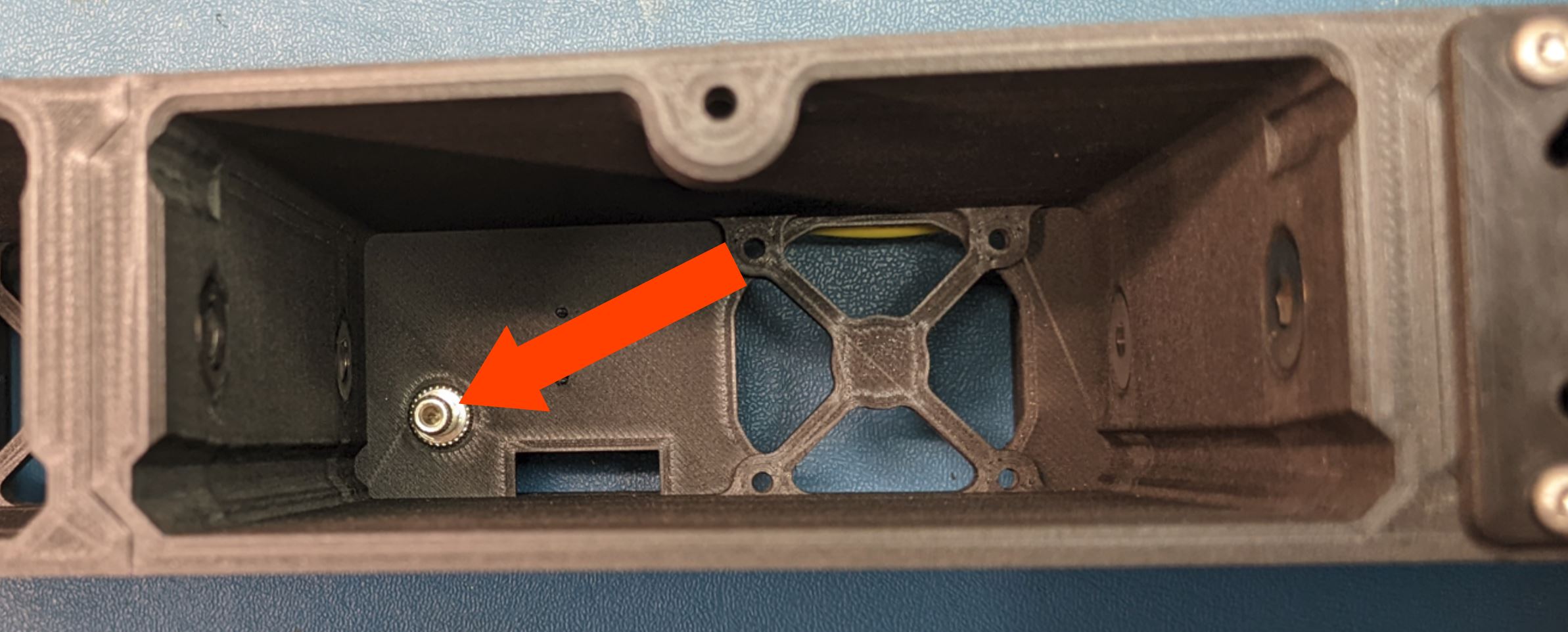
From the bottom of the module, look to make sure the two mounting holes in the switch align with the two holes in the bottom of the case. When the holes align, use use two #2-56, 7/16" LG FHMS to hole the switch in place.
Use two #2-56 nuts to secure the switch in place. Before tightening the nuts, give the switch a firm push to make sure it is as far forward (towards the front of the module) as possible.
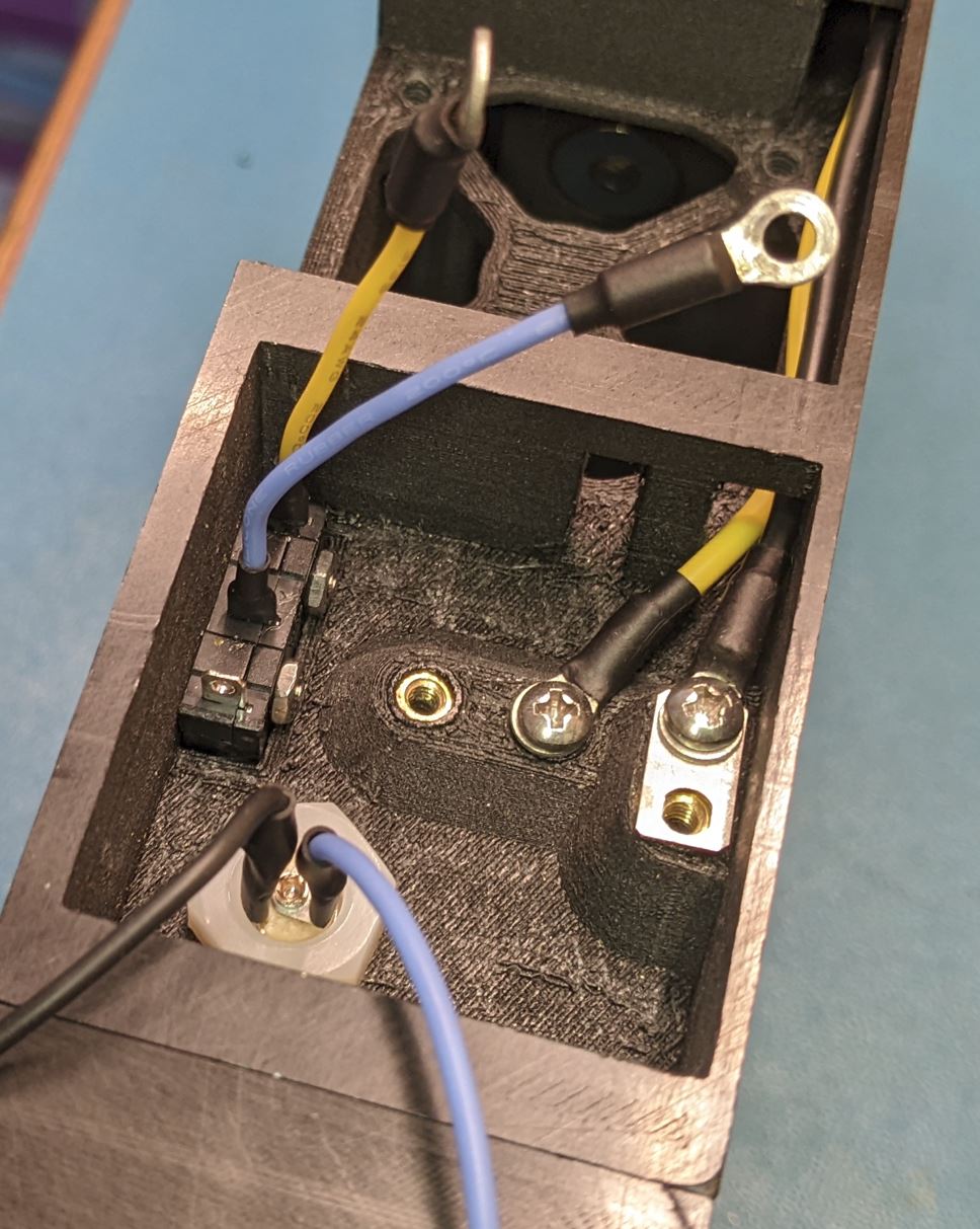
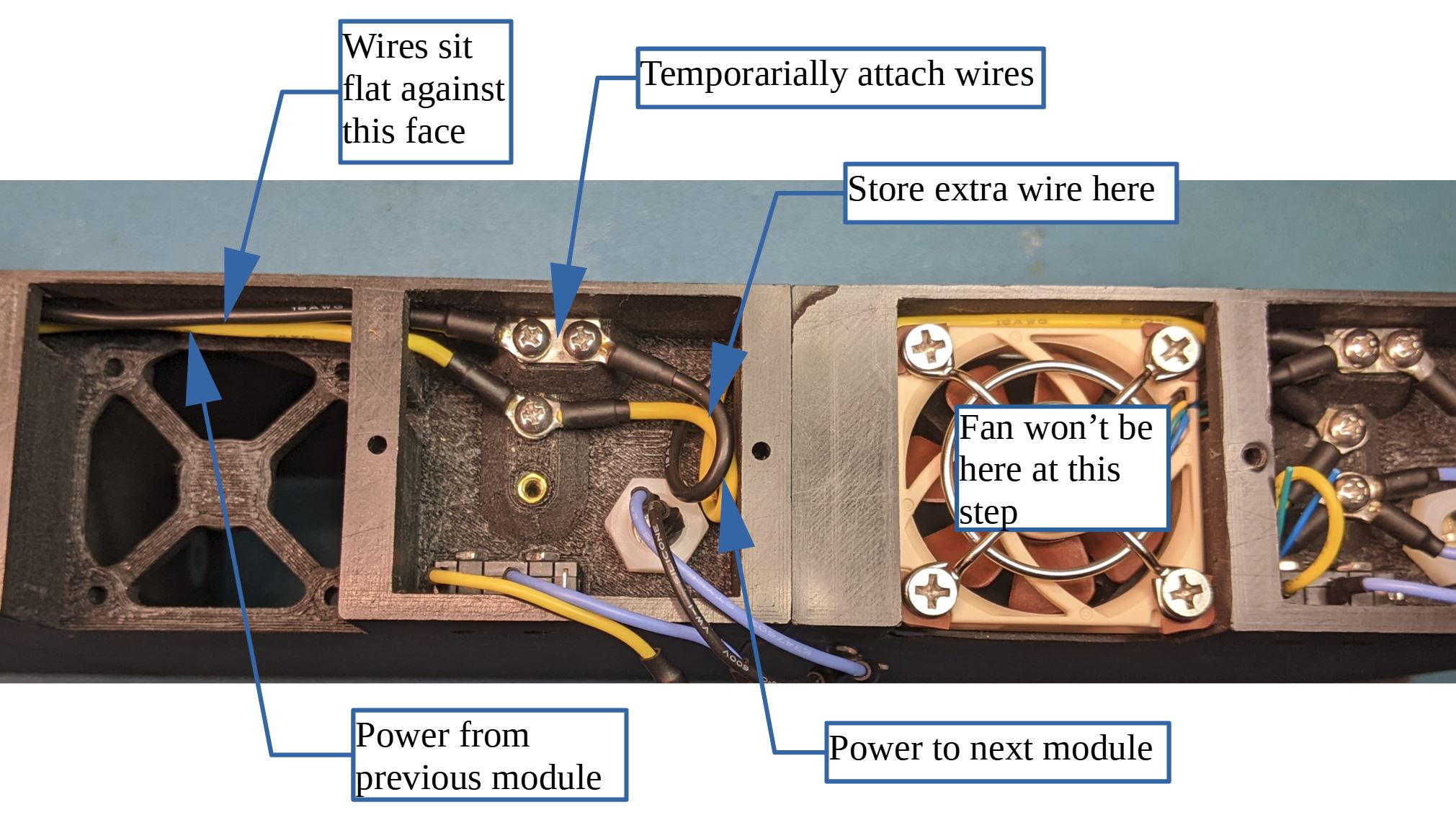
Arrange and screw down the transfer wires. Looking at the back of the case, wires from the left are from the previous module and wires to the right are going to the next module.
Attach the black ground wire from the left to the top left most screw. Place a jumper plate between the terminal and the threaded insert. Attach the yellow wire from the left to the screw terminal in the middle. Make sure that the two transfer wires from the left sit flat along the top of the case where they go over the fan cutout. Not required at this point, but you can also attach the transfer wires to the next module (to the right). You will want to make sure that the wires sit flat above the fan and any extra wire length is contained inside the wirebox near the connector.
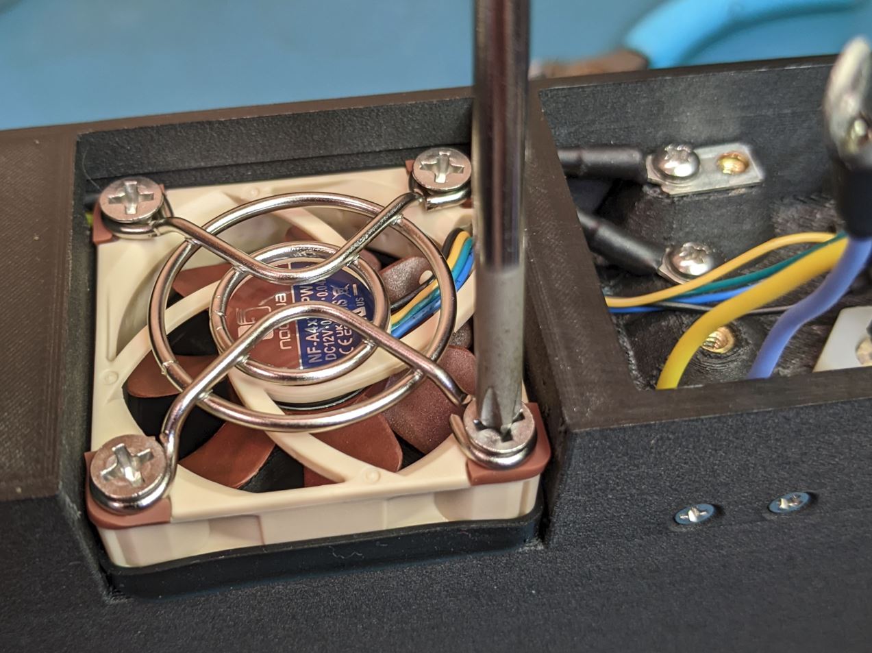
Fit the fan cushion on the inlet to the fan and set it into the cutout on the back of the case. As you install the fan, make sure the wires go through the cutout into the wirebox on the module.
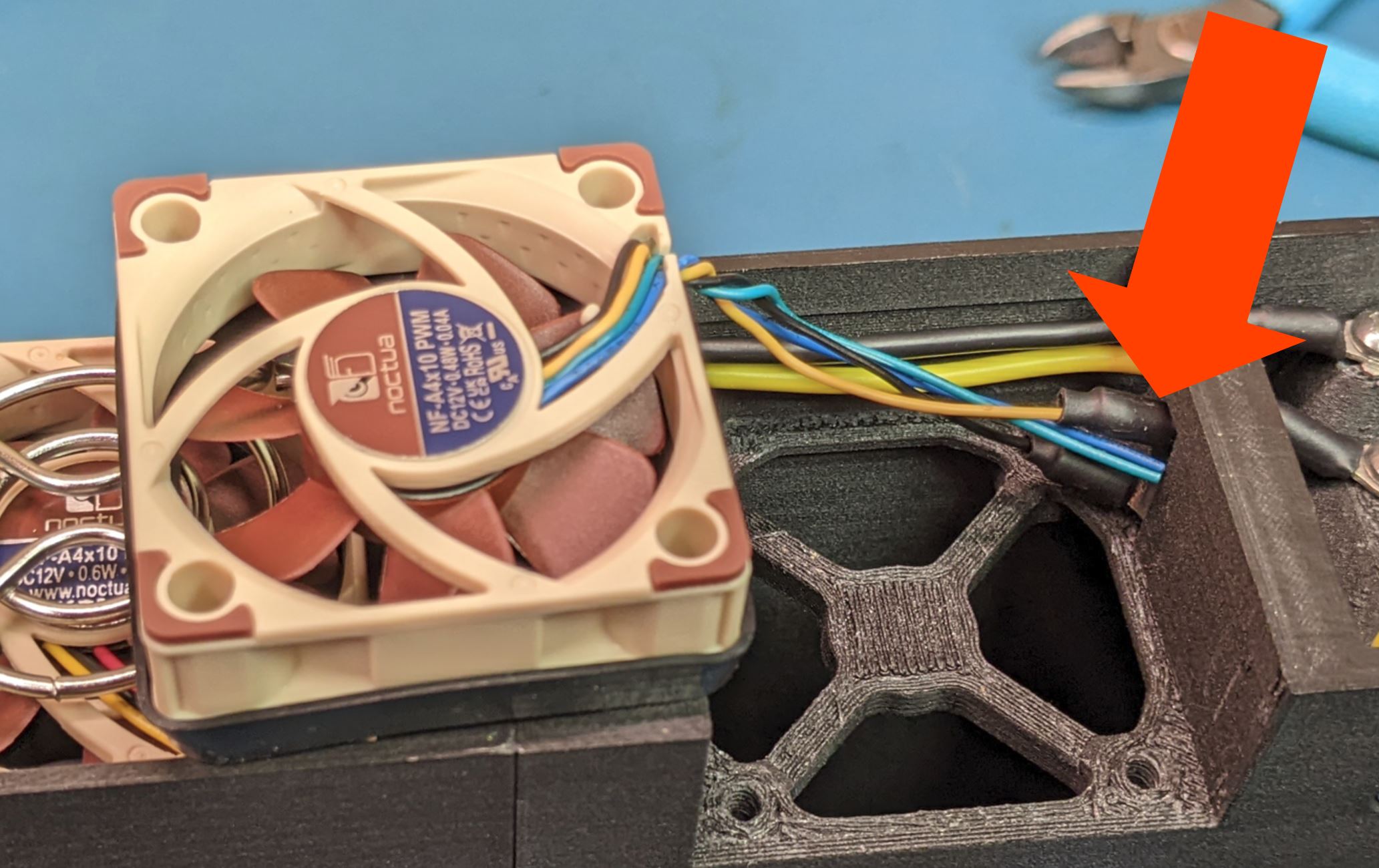
Set the fan into the cutout, making sure the cushion remains in place. Set the fan guard on the fan outlet and screw down with four #6 FHMS.
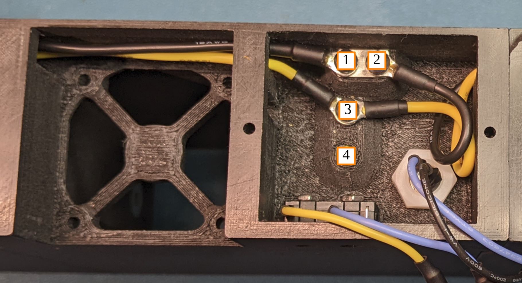
Make the final wire connections. Once all of the wires are on the screw, tighten the screws.
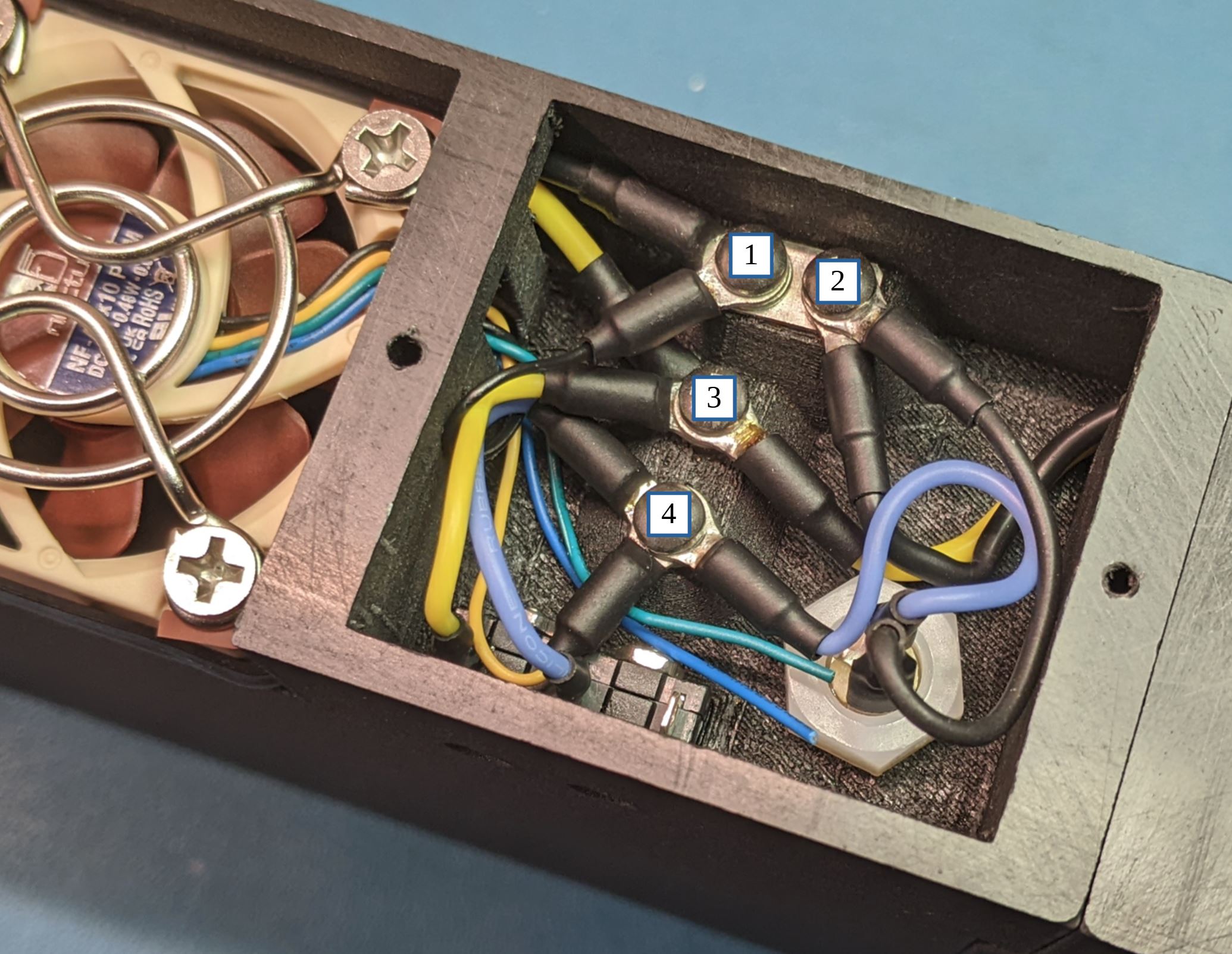
Terminal 1 (ground):
- Jumper plate on the bottom
- Ground (black wire) from the previous module
- Ground (black wire) to the fan
Terminal 2 (ground):
- Jumper plate on the bottom
- Ground (black wire) to the next module
- Ground (black wire) to the DC plug
Terminal 3 (12V):
- 12V (yellow wire) from the previous module
- 12V (yellow wire) to the next module
- 12V (yellow wire) to the switch
Terminal 4 (switched 12V):
- Switched 12V (blue wire) from switch
- Fan power wire (red or yellow)
- Switched 12V (blue wire) to DC plug
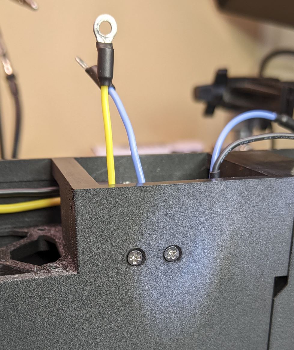
Slot a nut into the top of each of the modules as shown. The fit is loose, so if you turn the case over, the nuts will probably fall out.

Fit the wire covers over the wire compartments on the back of the device modules. Secure with two #2 self tapping pan head screws.

You can wait until you have all the modules installed before you do this. Turn on the power module. The fans on the device modules should not turn on. Reach in and press the switch lever. The fan on that module should start spinning when the switch is pressed.